Procedural Generation
Projecting procedural textures onto 3d surfaces
Background
A little bit of background before we dive right into projecting our textures onto 3d objects:
So far, we have only been working with one kind of shader program: Fragment shaders. A full shader program is comprised of both a Vertex and a Fragment shader. I can't do a good job explaining how these two things work in tandem, thankfully, there's a few animations that do it much better than I could explain Here. The two animations to look at are the one near the top, just under the first block of code, and another one further down, with a triangle with very jagged, pixelated edges.
The primary differences between the 'vertex' and 'fragment' shaders are:
- The vertex shader processes verticies
- The fragment shader processes pixels
- The fragment shader (typically) runs more times, and does more work
In this 'paper', we are moving on to write shaders for the Unity3d game engine. Shaders for this platform are a bit different, and come in many varieties. One method of producing shaders allows for controlling the legacy 'Fixed Function' pipeline. This is a bit less useful for us, since we want to be able to write more complex programs, rather than just telling the graphics card how to sample and blend texture images. We will be focusing on using Surface Shaders. This kind of shader works a bit differently than what we have been doing so far.
Unity's surface shader expects more than just a single color as output, instead, it expects a much larger struct, containing more information about the pixel.
    fixed3 Albedo;      // base (diffuse or specular) color
    fixed3 Specular;    // specular color
    fixed3 Normal;      // tangent space normal, if written
    half3 Emission
    half Metallic;      // 0=non-metal, 1=metal
    half Smoothness;    // 0=rough, 1=smooth
    half Occlusion;     // occlusion (default 1)
    fixed Alpha;        // alpha for transparencies
They also provide a version that takes also has a 'fixed3 Specular' property for specular highlight color. This struct is then used by a lighting function to produce the actual color of the pixel.
- Albedo is the primary output for surfaces, which is what recieves the light.
- Specular controls the color of specular reflections. By default, this is just white (100% of whatever light is being reflected)
- The Emission property is light that is always present (Emitted by the surface), and used for glows.
- Metallic and Smoothness properties determine the general reflectiveness of the surface, both to light sources and to the ambient environment reflections.
- Occulsion determines how exposed that part of the surface is to light. This adds to the appearance of depth on the surface.
- Alpha has no use for opaque surfaces, but can be used to either fade transparent surfaces, Or 'clip' pixels off of partial surfaces, like leaves.
Our 'surface' shader writes to these properties of a struct, and then that struct is unpacked and processed by a lighting function.
Unity's shader system is pretty extensible, and even allows for custom user lighting functions. The lighting function is what actually does what our fragment shaders were doing previously (determining a single color).
However, the presence of other properties gives us other places where we can provide details to make the surfaces have more detail.
For example, besides the Albedo property, we could vary the Metallic and Smoothness properties based on our noise functions, as well the Occulsion, Normal, and Emissive properties.
Unity's pipeline also does a lot of other useful stuff, like providing different information into the fragment/surface shaders, through a user-defined struct (Input) which can hold whatever information is needed, as well as allowing users to provide information themselves through custom vertex functions, as well as automatically compiling a number of different variants of the surface shader for different 'passes', and in different rendering modes. It also creates a way to pipe information about the shader for each 'material' that uses that shader program.
We use this system to grab the worldspace coordinates of the pixel that is being rendered, (The 'worldPos' field in the 'Input' struct) and we use that information to sample the noise fields to build the texture.
Unfortunately, Unity has retired their Web Player plugin, and doesn't properly support complex shaders in their WebGL pipeline, yet. So, there's no graceful way to embed these examples into the pages this time. Instead, there will be embedded images or videos.
Also, much of the stuff that has been done, has been ported to Nvidia Cg, (C for Graphics). Most of the common functions have been separated into cginclude files, similar to headers.
CGIncludes
- noiseprims.cginc - Holds the hash and basic noise functions
- fbm.cginc - Holds the fractal noise function
- voroni.cginc - Holds the voroni noise functions
- fbmnormal.cginc - Holds a helper function to generate normals for surfaces
- procheight.cginc - Holds a helper function to parallax surfaces
For starters, lets look at a 3d-projection of the camo created in the last 'paper':
Camo Surface Shader Code
-
Code (ITS BIG) more_vert
Shader "Procedural/Camo" {
    Properties {
        [Toggle(SWIZLE_OCTAVES)] _SWIZLE_OCTAVES("Swizle Octaves", Float) = 1
        _Color1 ("Color 1", Color) = (.490,.431,.294,1)
        _Color2 ("Color 2", Color) = (.274,.196,.059,1)
        _Color3 ("Color 3", Color) = (.196,.235,.098,1)
        _Color4 ("Camo Base Color", Color) = (.098, .078, .094, 1)

        _Clips ("Clips", Vector) = (1.4, .17, .29, .26)
        _Glossiness ("Smoothness", Range(0,1)) = 0.333
        _Metallic ("Metallic", Range(0,1)) = 0.395

        _Seed ("Seed", Float) = 13337.13

        _Octaves ("NoiseOctaves", Range(1, 12)) = 4
        _DiffLayers ("Difference Noise Layers", Range(1, 8)) = 3
        _DiffNoiseJump ("Difference Noise Jump", Range(1, 8)) = 2.5
        _Persistence ("NoisePersistence", Range(0, 1)) = .596
        _Scale ("NoiseScale", Float) = 2.15


        _BumpOctaves ("BumpOctaves", Range(1, 8)) = 5.0
        _BumpScale ("Bumpiness Spread", Range(1.337, 33.37)) = 4.5
        _BumpPersistence ("Bump Persistence", Range(0, 1)) = .579
        _BumpAmt ("Bumpiness Amount", Range(.01, 2)) = 1.46

        _Offset ("NoiseOffset (x,y,z) * w", Vector) = (0, 0, 0, 1)
    }

    SubShader {
        Tags {
            "RenderType"="Opaque"
            "DisableBatching" = "True"
        }
        LOD 200

        CGPROGRAM
        #pragma surface surf Standard fullforwardshadows
        #pragma target 3.0
        #pragma multi_compile __ SWIZLE_OCTAVES

        #include "inc/noiseprims.cginc"
        #include "inc/fbm.cginc"
        #include "inc/fbmnormal.cginc"

        struct Input {
            float3 worldPos;
            float3 viewDir;
        };

        half _Glossiness;
        half _Metallic;
        fixed4 _Color1;
        fixed4 _Color2;
        fixed4 _Color3;
        fixed4 _Color4;
        int _DiffLayers;
        float _DiffNoiseJump;
        float4 _Offset;
        float4 _Clips;

        //Difference noise function
        float diffNoise(float3 pos) {
            float v = nnoise(pos);
            for (int i = 0; i < _DiffLayers; i++) {
                pos.z += _DiffNoiseJump;
                v = abs(v-nnoise(pos));
            }
            return v;
        }
        void surf (Input IN, inout SurfaceOutputStandard o) {
            resetNoise();

            //Translate world position into local model position
            float4 wpos = float4(IN.worldPos, 1);
            float3 pos = mul(unity_WorldToObject, wpos);
            pos += _Offset.xyz * _Offset.w;

            //Pretty much the same as the GLSL shader
            float4 c;
            float clip4 = diffNoise(pos);
            if (clip4 < _Clips.w) {
                pos.z -= 3.0;
                float clip3 = diffNoise(pos);
                if (clip3 < _Clips.z) {
                    pos.z -= 5.0;
                    float clip2 = diffNoise(pos);
                    if (clip2 > _Clips.y) { c = _Color1; }
                    else { c = _Color2; }
                } else { c = _Color3; }
            } else { c = _Color4; }

            //Assign output color
            o.Albedo = c.rgb;
            //Assign surface orientation
            o.Normal = fbmNormal(pos);
            //Shinyness
            o.Metallic = _Metallic;
            o.Smoothness = _Glossiness;
            //Does nothing, but is still output
            o.Alpha = c.a;
        }
        ENDCG
    }
    FallBack "Diffuse"
}
Wow, that was a huge amount of stuff. It starts with the properties block. This defines what data is piped into the shader from the engine, allowing people other than the programmer to define things about the shader. Each of the lines in this section corrospond to a variable defined below (the variables starting with _). Then there's a bunch of #include directives pointing to some of the cginc files listed above, and some other compile directive stuff. Below, towards the bottom, the last few lines assign to the surface outputs. The middle part is still relatively the same.
The surface produced by this shader (with default settings) looks like the following:
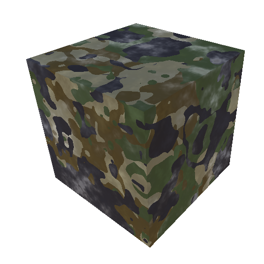
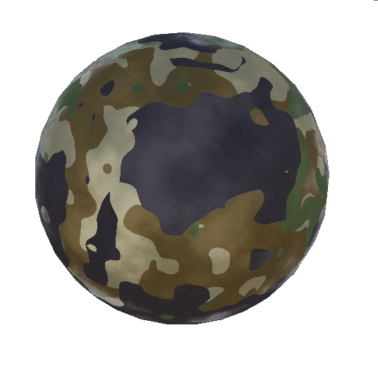
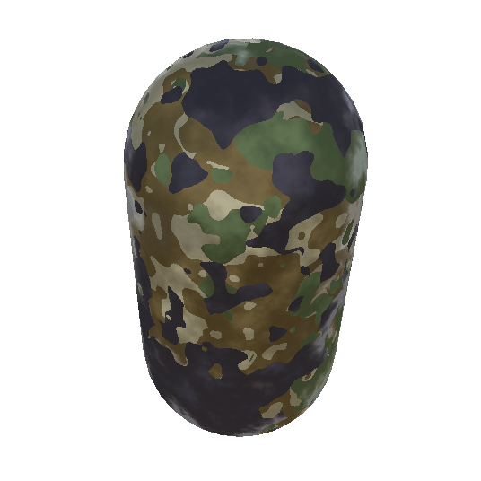
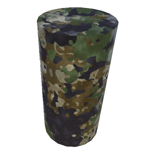
Lookin pretty good. Another benefit from using procedural textures, is it's extremely easy to modify what the surface looks like.
Changing shader properties
(Click to expand)
-
Basic Properties more_vert
These properties apply to all of the procedural shaders, as they effect variables defined in 'noiseprims.cginc', which are used by pretty much every noise function. They have similar effect on each different shader.
_Seed
Changes quickly changes the spread of the noise This allows for basically an unlimited number of variations to a texture to be made._Octaves
Changing the octaves changes the deepness of the fractalization of the noise._Persistence
Persistence changes the amplitude of deeper fractal layers._Scale
Scale changes the base 'frequency' of the noise field.
-
Bumpiness Properties more_vert
These are properties I created that have similar effect across surfaces that have 'bumpiness'
_BumpAmount
Changes the maximum bumpiness of the surface._BumpSpread
Changes the base 'frequency' of the bumpiness._BumpPersistence
Changes the roughness of the bumpiness
-
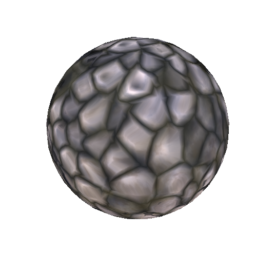
Camo Properties more_vert
These are properties specific to the camo shader
_Clips
Determines the cutoffs for each region_DifferenceLayers
Makes the texutre have more smaller lumps and thinner ribbons.
So, changing the properties changes the noise fields, or how the samples are used to generate the texture. The parameters that can be piped into shaders are pretty limitless, as are the kinds of things that one can do with the shaders.
Heres a bunch of other, similar effects I've written using the same noise primitives and CGIncludes. The first two, 'Marble' and 'Digital Brain', I didn't come up with myself, like with the camo pattern, but the rest are all creations of my own. The Camo, Marble, and Tech effects I wrote to get my bearings in the world of making shaders. I then used similar techniques to create the other effects.
Click one to show more info about it.
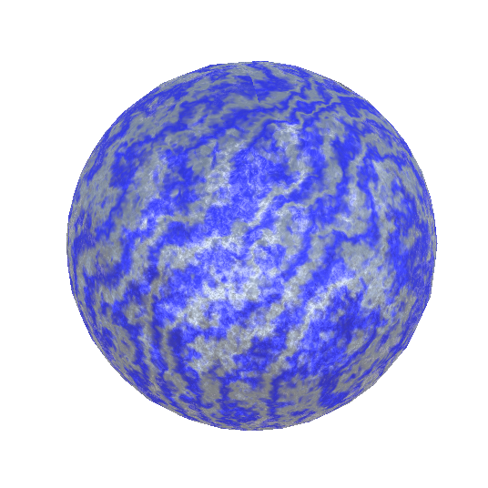
Marble
Code Here
This is one of the simpler effects. Again, I didn't come up with this myself, but have seen it used in numerous places. The meat of the effect is the calculation of the value:
float v = ( 1 + sin( ( pos.x + nnoise(pos, _Factor) ) * 50 ) ) / 2;
Which is used to lerp between two colors. The inputs to the sin function are the x position (which always increases) and the noise value at the point (which is essentially random). This creates a sort of 'grain' in the surface. This effect might be good for creating a bit of regularity in a surface, such as the grain of wood, or layers in sandstone.
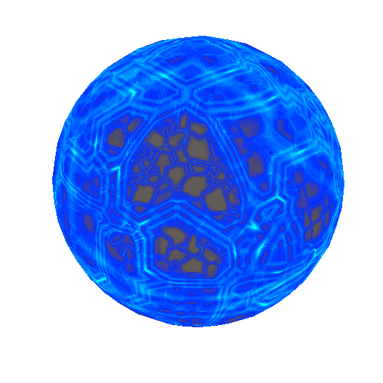
Digital Brain
Code Here
This is a bit of a different effect. It's also transparent, so it writes to the o.Alpha output field, and is compiled with the pragma alpha:fade.
It's a pretty simple effect that is a bunch of layers of voroni noise, but the neato part is the 'electrons' moving across the 'wires'. On octaves deeper than the first, there's an additional sample of the noise function used to animate the electrons. This extra field is panned across the first field, which is what makes the electrons move. Only a small section of the field is animated this way (sample value between certain values), so the electrons are confined to the 'wires' instead of the 'cells'.
This is the last effect I used someone else's work on. The original effect I based this on can be found Here. This is one of the effects that I got inspired by, and got me writing these effects in the first place, and even after all this time (and especially that I now undestand exactly how it works), I still find it a really cool effect.
'Lumpy'/Stones
Code Here
Another variant Here
This effect turned out way better than I expected. I used a technique for parallax, where the height of the surface is controlled by a Voroni Cellular noise. The parallax calculation is fairly simple for the visual interest it adds. It's included in the 'procheight.cginc' file:
inline float3 parallax3d(Input IN, float3 h) {
    const float3 nrm = normalize(IN.wNormal);
    const float hv = h * _Parallax - _Parallax * _Bias;
    const float3 eye = normalize(IN.viewDir);
    float3 dir = eye - nrm * dot(eye, nrm) / dot(nrm, nrm);
    return hv * -dir;
}
That is used to offset the sample for the actual texture. The eye direction (dir) on the last line can be flipped to taste, neither looks perfect, as this technique works much more simply in on 2 dimensional textures, and not that well on 3 dimensional textures. Parallax calculations in 2d and 3d both rely on projecting the eye vector onto the surface and offseting the texture sample in that direction by some distance, based on the height sample.
Then, the noise field is re-sampled at the offset position. Then, the result is used to calculate albedo, normals, and is also applied to the 'Glossiness' and 'Metallic'ness of the pixel. I added another feature (_Polish) which changes how much 'Glossiness' and 'Metallic'ness the pixel has based on the 'height' of the pixel.
Not being content, I took a technique from the previous 'Digital Brain' effect, and added another set of samples to the voroni noise function, this time, 3 of them, at different frequencies. Unlike in digital brain, this is applied across the entire space, rather than just along the 'circuits'. Then, the samples panned and blended, creating an animated, liquid covered texture.
This effect comes out of the 'water' samples affecting the height (and thereby, the parallax of any pixel), as well as a bit of color. This gives the 'lower' regions between the stones some color. One cool side effect of the way this is done, is the panning is in whatever space the texture is in (world or local). When using the worldspace, the water always flows in the worldspace direction (as shown in webm below).
I then modified this water texture to be like a slime covered rock, panning at a slower speed, with lower amounts of higher frequency noise blended.
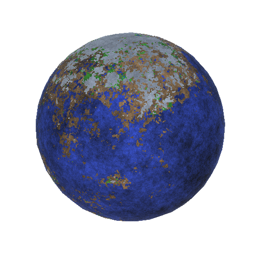
Planet
Code Here
This one is another adapted 2d texture, but one I had made earlier when experementing with 'mode7' like projections.
My original effect can be found Here
The original effect sampled the noise function a few times, for 'height' and 'moisture' values, then, like the camo effect, 'Clips' the texture into different regions, but instead, based on the combination of the values.
This adaptation works much the same way, but with improved surfaces, and adjustments to 'height'/'moisture' based on the distance from the 'equator' (or to the x/z plane).
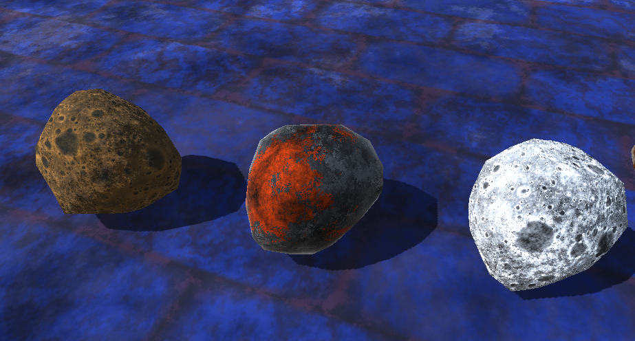
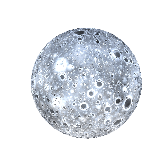
Moon
Code Here
This one was very interesting to write, and looks very convincing until you get right up close to it. It's a simple Euclidean-distance voroni noise, filtered and processed in such a way that not all holes pass. Then, the edges of the holes are adjusted they are smooth, rounded craters, with a slight lip around the edge. And, of course, the craters are fractalized, and it uses the same height-parallax technique the 'Lumpy' shader does.
Going into more detail, the craters are determined by the distance to the closest point. That distance is applied to a curve, roughly as follows:
There is some smoothing applied within the shader for this curve, but this makes it so only positions very close to feature points become craters, there's a nice lip at points just outside of those craters, and the rest of the points not close to feature points are flat.
The height parallax then adds to the illusion that there is depth on the surface,
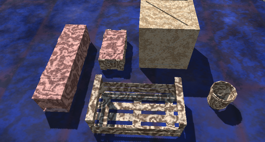
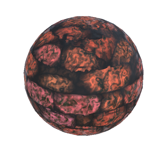
Bricks
Code Here
This is likely the most complicated shader I have written so far. There's a ton of parameters for all sorts of things, such as the size of the bricks, offsets per 'layer', factors for 'relaxing' the noise, blending different noise layers, and changing the border size between the tiles.
The basic effect works by this process:
- Taking the sample point, and determining the 3d cell it resides within
- Blend between 'grout' and 'brick' based on the distance from the sample point to the cell edges.
- Sample 'texture' for height value, offset sample point with parallax
- Re-determine cell, 'grout'/'brick' blend etc.
- Sample offset sample point for color, normal
Then, I decided to apply the water texture on-top of the bricks, much like the 'Lumpy' effect. This is applied the same way (Once for the height/parallax, and once for color).
Here are the shaders applied to some models that were graciously given to public domain by 'Yughues' of Open Game Art: